

- Akademische Forschung und Lehre
- Geräte des KIT
- Mitarbeiter des KIT
- siehe Lizenzbedingungen
-
STAR-CCM+
-
CFD program for the calculation of flows, heat propagation, combustion and chem. Reactions and much more.
- Contact:
- Contact Person:
- Links:CD-adapco Homepage
About STAR-CCM+
Simcenter STAR-CCM+ by Siemens is a comprehensive, multidisciplinary Computational Fluid Dynamics (CFD) and multiphysics simulation platform designed to integrate an entire engineering workflow into a single user interface. Rather than requiring separate programs for geometry cleanup, meshing, solving, and post-processing, it allows students and researchers to handle everything seamlessly in one place. The software is widely used in academia to simulate how products operate under complex, real-world physical conditions, capturing fluid flow, heat transfer, solid mechanics, and chemical reactions. Furthermore, its architecture is highly optimized for High-Performance Computing, enabling massive engineering models to scale efficiently across university cluster nodes.
Our academic license provisions a robust environment across concurrent seats, covering core computation, advanced optimization, and native CAD data translation. For standard simulations, the license includes ccmpsuite to access the central solver workspace and ccmppowerplus to drive parallel processing across multiple CPU or GPU cluster cores. To support intelligent design exploration, the site license features a pool of DOEtoken units, which allows researchers to automate parametric sweeps, run deep optimization cycles, and conduct complex Design of Experiments without consuming standard seat licenses. Data ingestion is streamlined through cadexchange and JTOpen, alongside dedicated, bidirectional direct links for major CAD suites including Siemens NX via star-nx, CATIA V5 via star-cat5, PTC Creo via star-proe, and Autodesk Inventor via star-inventor.
Beyond standard fluid dynamics, the license unlocks highly specialized physics frameworks and targeted application assistants. For advanced automotive and energy research, the software includes batterysim and batterydesignstudio for electrochemistry and battery pack thermal management, alongside dars-ign, proice, enablestarice, and enablereactivemodels for internal combustion engine dynamics and chemical kinetics. For complex free-surface fluid behaviors like sloshing or splashing, meshless CFD modeling is supported through sphflow and sphsim for Smoothed Particle Hydrodynamics. Setting up industry-specific simulations is accelerated using a dedicated App-Suite, featuring app-marine for hull resistance and hydrodynamics, app-turbo for rotating machinery like pumps and turbines, app-mixing for industrial stirred reactors, and app-cat for catalytic converters. Finally, the license integrates innovatesuite for high-fidelity post-processing visualization and pcfea to map fluid forces directly into structural finite element analysis.
Current Licensed Software Version
STAR-CCM+ 2606
STAR-CCM+ 2602
STAR-CCM+ 2510
STAR-CCM+ 2506
STAR-CCM+ 2502
Installation
The installation files for the latest version of the software, along with network licensing information are available on our FTP server. STAR-CCM+ is installed and available on our Linux clusters, BwUniCluster3.0 and Horeka.
Note: Installation files for versions that are not listed above can be obtained upon request by contacting scs-contact∂scc kit edu.
Licensing
Network License: To use the network license, please specify the license server name and port during installation as indicated in the network license configuration file available on the FTP server. An active internet connection is required to use the software. If you are accessing it from outside the KIT network domain, please connect via VPN in order to reach the license server. For instructions on setting up and using the VPN, please refer to the link: Remote Access (VPN)
Excerpt from the license agreements
The SCC has purchased an academic license of StarCCM+ which, according to Siemens Industry Software GmbH (formerly CD-adapco Group ), allows the following usage:
"...
d) Academic License. When a Software License is designated as an Academic License, Licensee represents and warrants that it is an academic institution or other nonprofit organization. The Academic Software License permits Licensee to use the Software for purposes of teaching, degree-granting programs, or research that are part of the academic teaching processes conducted by Licensee. Academic licenses are not intended for use in commercial data processing for the purpose of generating profit.With this in mind, the Licensee agrees that results obtained using the Software may be publicly shared or published. The Licensee agrees to refer to the use of CD-adapco's Software in all appropriate scientific academic publications and to provide the Licensor with copies of such published material. Material on/in which CD-adapco's trade name, trademarks or logos appear is subject to CD-adapco's policies applicable to such use..."
The complete license agreement for the use of CD-Adapco software products can be found on the FTP serverftp://ftp.scc.kit.edu/pub/campus/STAR-CCM+/ and on the CD-Adapco website http://www.cd-adapco.com/purchase-license-agreement-pla (ENG) /(DE).
Quick Start Guide
Interactive use of STARCCM+
The editing of a STAR-CCM+ project is done via a graphical user interface and there especially by creating and editing objects in an object tree. The STAR-CCM+ GUI is started
- under Windows: by clicking on the STAR-CCM+ icon on the desktop or via Start --> CD-adapco --> STAR-CCM+Version for Windows, where Version is the current version number.
- under Linux: with the command starccm+.
Then a window opens and one selects in the file menu New Simulation ... or Load Simulation ... from the file menu. In the following STAR-CCM+ works on a single file, namely projekt.sim, where the name is assigned at the first save and is located above the object tree (in the picture cyclone).
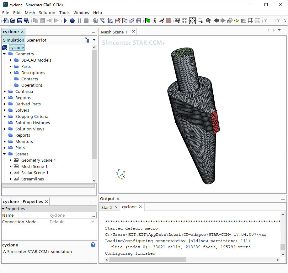
The figure shows the typical desktop with the object tree in the left half. The individual objects are selected with the left mouse button. Clicking on them with the right mouse button opens a context menu that can be used to edit the object.
The process of a STAR-CCM+ project is generally as follows:
- Import from CAD programs or construction of geometries with the 3D Modeler.
- Editing and repair of surfaces
- Definition of boundary conditions
- Selection of the meshing model
- Definition of the physical model
- Meshing
- Preparation of the postprocessing
- Specification of the solver and start of the calculation
- Postprocessing
Import from CAD programs or construction of geometry with the 3D Modeler
The starting point of a model is the geometry, which is either created in the GUI with the 3D Modeler or imported. Surfaces can be imported in CAD format or in the format of other CAE programs:
- Parasolid (.x_t and .x_b)
- IGES (.igs and .iges)
- STEP (.stp and .step)
- STL
- PATRAN and NASTRAN shells (.pat and .nas)
- CD-adapco format, e.g. exported from Pro-STAR, the preprocessor of STAR-CD (.dbs and .inp)
- CATIA V4 and CATIA V5
- SolidWorks (.sldprt and .sldasm)
- ProE (.prt and .asm)
- Autodesk Inventor (.ipt and .iam)
- VDA
Volume meshes of other CAE programs can also be imported, e.g. FLUENT, STAR-CD, Nastran, EnSight and others.
Depending on the imported format, so-called parts are created as the first objects, as well as by the 3D modeler. Parts must be assigned to so-called regions before meshing. When importing meshes from other CFD programs, e.g. STAR-CD, regions are generated directly, which are hierarchically built up from volumes and bounding edges. At the same time a Geometry Scene is created. Scenes are 3D graphical representations of the geometries and results in the graphics part of the GUI. Regions can be composed of several areas separated by interfaces, which are the internal borders. The interfaces also appear as objects and physical properties can be assigned to them.
Editing and repairing surfaces
Imported surfaces from CAD programs may need to be further processed and repaired. This will not be discussed further here. Examples can be found in the tutorials.
Definition of boundary conditions
In the region node of the object tree the continua and the boundary conditions are shown. By clicking with the right mouse button you can change the names. Double-clicking with the left mouse button opens an editor window in which you can define the properties, in this case the boundary conditions, e.g. symmetries, inlet or outlet boundary condition, pressure boundary condition or simply wall boundary condition.
Selection of the meshing model
The meshing model refers to the continua objects in the object tree. A continuum in the sense of STAR-CCM+ is the combination of the meshing model related to an area in which the simulation takes place, the Mesh object, and the physical model that plays a role there, the Physics object. Both objects are created by right-clicking on Continua and selecting Mesh Continuum or Physics Continuum from the New context menu. First select the former and then set the mesh properties (type of mesh, global mesh size, etc.). You can also set the surface meshes on the boundary surfaces to be set individually. Then, in the Boundary object nodes below the Regions object, the mesh properties can also be set locally, one after the other.
Definition of the physical model
The physical model of a Continuum object is defined by clicking the right mouse button on the Physics object and selectingSelect models ... in the context menu. Then click on the physical properties to be realized in the model, e.g. dimensionality, time response, material, solver, turbulence model, etc.
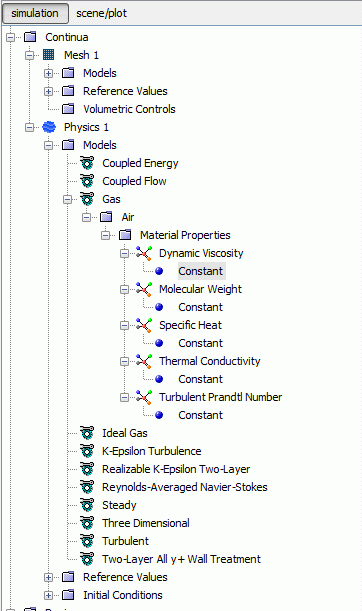
The object tree under the Physics 1 object then has e.g. the appearance shown above. Under Gas, the Air node can be unfolded, which contains the physical constants for air. Here you can enter the values of another gas and change the name accordingly. Under the Initial Conditions node the initial conditions for pressure, velocity, temperature and the turbulence variables are set.
Up to this point, the Continuum object is not yet assigned to a geometric area. This is done by editing the continuum area(s) under the Regions node and selecting the corresponding Physics Continu um and Mesh Continu um.
Meshing
Initially, one can only mesh the surfaces to get an estimate of the mesh quality. The surface mesher is started either via the corresponding icon in the toolbar or via the Mesh menu and Generate Surface Mesh. Afterwards, the mesh sizes can be changed or the volume mesher can be started immediately, also via the toolbar or via the mesh menu and Generate Volume Mesh.
Preparing the postprocessing
Scenes are objects that graphically represent different aspects of the model. There are 4 types of Scenes:
- Geometry Sc ene to represent the geometric parts and regions.
- Mesh Scene to represent the mesh on the surfaces of parts.
- Scalar Sc ene for displaying contour plots of scalar quantities on surfaces of Parts and Derived Parts
- Vector Scenes for displaying vector quantities on surfaces of Parts and Derived Parts
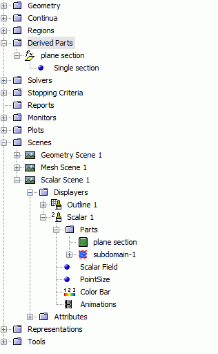
A Scene node in the object tree consists of 2 subnodes Displayers and Attributes in which the quantities to be displayed and the parts on which they are displayed are specified, as well as background, lighting, section planes, etc. In the node Derived Parts you can define new areas: Planes, spherical or cylindrical surfaces and isosurfaces, but also streamlines and probes.
By clicking with the real mouse button on the Scene node, you can create a new scene and define the sizes to be displayed and the display areas.
Specification of the solver
In the Solver node of the object tree you can select the solver and specify its properties. In the node Stopping Criteria the length of the simulation, i.e. the criterion for the termination, is specified. Depending on the type of simulation you can define with
- Maximum Steps defines the maximum number of iterations
- Stop File defines the path of a file named ABORT, so that if this file exists, the job will be stopped.
- Maximum Physical Time defines the end time for a transient simulation
- Maximum Number of Inner Iterations for a transient simulation defines the maximum number of iterations in one time step.
It is also possible to control the simulation via a monitor (see the STAR-CCM+ User's Guide).
The simulation as such is started via the menu sequence Solution --> Run or via the icon in the toolbar. During the simulation you can activate one of the Scenes and watch the development of one of the plots.
Postprocessing
Postprocessing is done simply by activating the corresponding scene and selecting the part on whose surface the contour or vector representation is to be plotted. New scenes or extensions of already defined scenes are also possible.
StarCCM+ on the Linux clusters
On the SCC parallel cluster bwUniCluster a modular concept is used. Before you can work with the StarCCM+ product, you must first load the appropriate module. You can get all available software modules by selecting
module avail
in the menu. To load the module of the current version of StarCCM+, type the following:
module load cae/starccm+/2302
To ensure that the Linux clusters run as smoothly as possible, the jobs submitted are managed by a job management system. For more details, see https://wiki.bwhpc.de/e/BwUniCluster_2.0_Slurm_common_Features.
To facilitate access for the user, the StarCCM+ call"starccm+job" has been provided (the module must be loaded beforehand):
starccm+job
-j simulation name (necessary)
-t CPU time in minutes (necessary)
-m total main memory requirement in MByte (necessary)
[-n number of nodes; default: 1]
[-p number of processors; pre-population: 1]
[-q queue type/ partition; default: single/ multiple]
[-T Real time in minutes]
[-s Text string with further options]
The following is an example for the bwUniCluster:
module load cae/starccm+/2302
starccm+job -j MyModel.sim -t 60 -m 90000 -n 2 -p 20
Alternatively, a startup script as described below can be used to submit a job from starccm+ to the batch system. Here is an example script for a multinode job on the bwUniCluster multi_node_job.sh:
#!/bin/bash
#SBATCH --nodes=2
#SBATCH --ntasks-per-node=20
#SBATCH --partition=multiple
#SBATCH --time=0:60:00
#SBATCH --mem=90gb
module load cae/starccm+/2302
source starccmplus.init
time starccm+ -batch -rsh ssh -mpi intel -on ${hostlist} MyModel.sim
The job is submitted as follows:
sbatch multi_node_job.sh
If running GPGPU with Star-CCM+ the script looks like as follows
#!/bin/bash
#SBATCH --nodes=1
#SBATCH --ntasks-per-node=20
#SBATCH --time=0:60:00
#SBATCH --mem=40gb
module load cae/starccm+/2302
source starccmplus.init
time starccm+ -batch -gpgpu auto -rsh ssh -mpi intel -on ${hostlist} MyModel.sim
The job is submitted as follows:
sbatch -p gpu_4 gpu_job.sh
More about usage of GPGPU on the bwUniCluster s. https://wiki.bwhpc.de/e/BwUniCluster_2.0_Slurm_common_Features#GPU_jobs